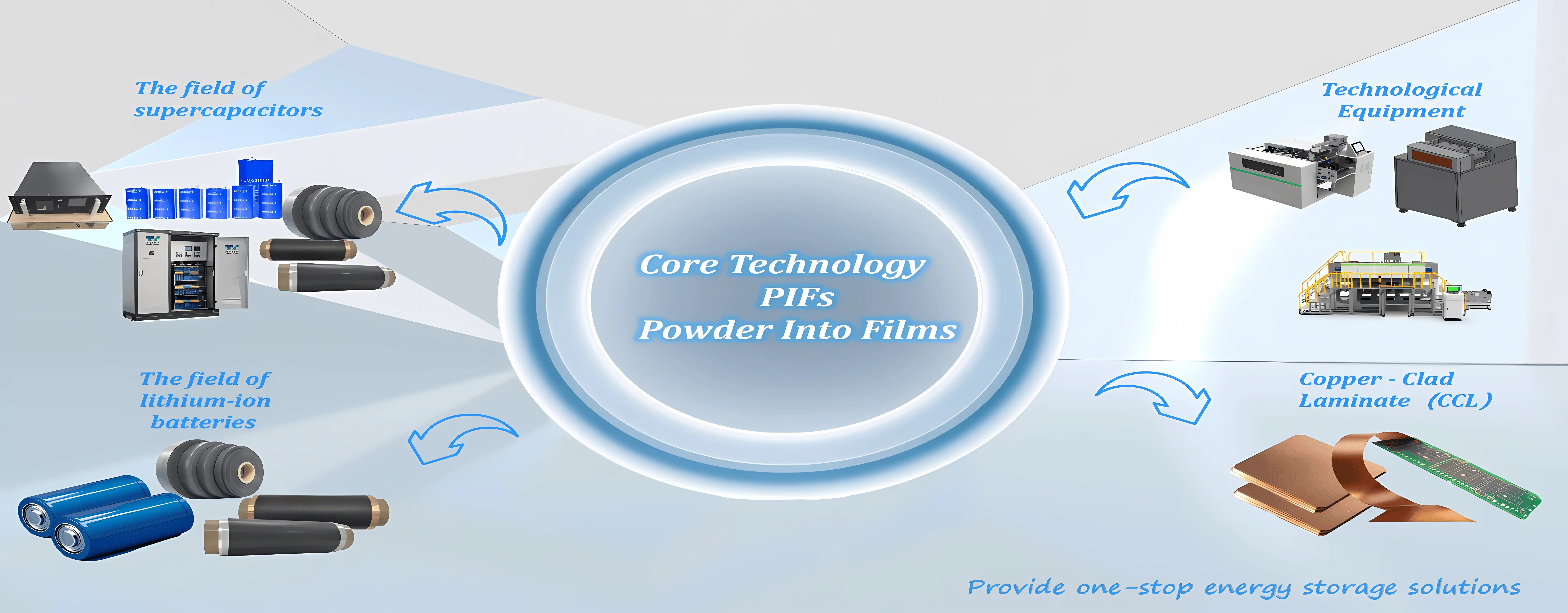
1. Raw Material Preparation
The dry electrode processing begins with the dry blending of three core components:
Active material (e.g., NCM for cathodes, graphite for anodes) determines energy density.
Conductive additives (carbon black, CNTs) compensate for PTFE’s insulation.
PTFE binder (3–5% by weight) replaces solvents, forming a fibrillated network.
Critical requirement: Homogeneous mixing to prevent agglomeration, typically using high-shear planetary mixers.
2. PTFE Fibrillation
During blending or subsequent roller shearing, mechanical force induces PTFE fibrillation—where the binder forms a 3D fibrous mesh. This:
Enhances electrode mechanical strength.
Eliminates the need for solvents (unlike wet slurry processes).
Maintains thermal stability (−200°C to +260°C).
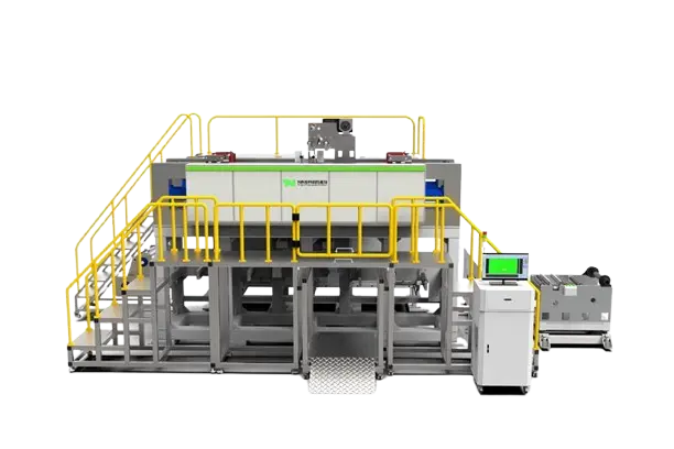
3. Calendering: Dry Powder Compression
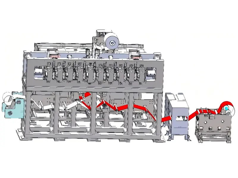
The dry mixture is fed into a calender (heated rollers at 80–120°C) under high pressure (10–50 tons) to:
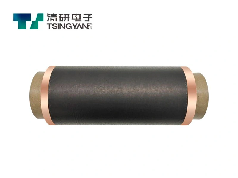
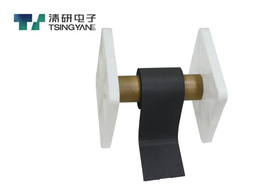
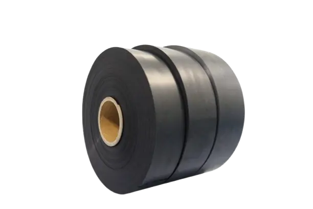
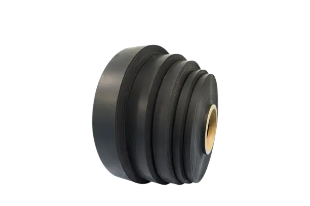
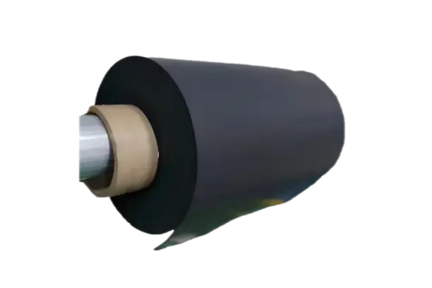
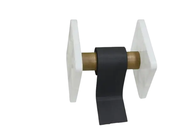
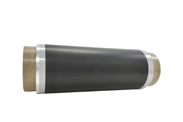
Compress the powder into a freestanding electrode film.
Optimize density (e.g., ~3.4 g/cm³ for anodes).
Challenge: Balancing pressure to avoid cracking the Al/Cu current collectors.
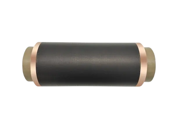
4. Lamination to Current Collectors
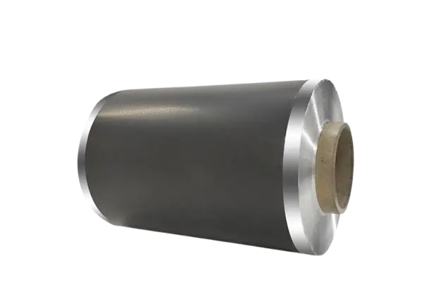
The calendered film is thermally bonded to:
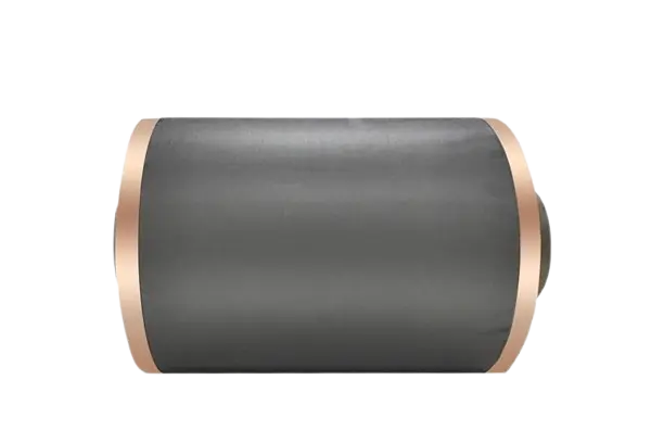
Aluminum foil (10–20 µm, cathodes) or copper foil (anodes).
Surface treatments (e.g., laser texturing) improve adhesion.
Key parameter: Precise temperature/pressure control to prevent delamination.
5. Final Assembly & Validation
The dry electrodes are:
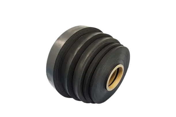
Slit to required dimensions.
Integrated into battery cells (e.g., stacked or wound).
Validated for conductivity, porosity, and cycling performance.

 English
 日本語
日本語 한국어
한국어 français
 Deutsch
 Español
 italiano
 русский
 português
 العربية
 tiếng việt


_Technology.webp)
